Blog - Fibre optic measuring instruments
As well as copper installations have measuring instruments, in fibre optic installations it is also necessary to have fibre optic measuring equipment, with which to check that everything is working correctly (read power values, detect faults, etc.). In this new blog entry we list the main equipment available at Keynet Systems :
Visual Fault Locator VFL
To check a fibre for continuity with the naked eye, we use a visual fault locator (VFL). This is a device that emits visible laser light, usually red, and we can see whether or not it reaches the other end to detect a fault or identify a fibre in a bundle.

The beam of light can be continuous or discontinuous and, depending on the power of the model, it can be used over longer or shorter distances.
Optical Power Meter OPM
Keynet Systems’ fibre optic measurement equipment includes the OPM-71PC power meter. This is able to measure the light power reaching it at different pre-programmed wavelengths. They typically store the measurements in an internal memory.

It is commonly used in conjunction with an emitter of known power.
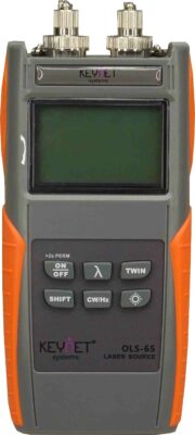
OLS laser emitter
Another fibre optic measurement device is the OLS laser emitter. This is an emitter at known power, which is capable of emitting at different preset wavelengths, so that an accurate reading can be made with an OPM. Both devices must be synchronised during setup before starting measurements, so that the meter obtains the information on the wavelength at which we are going to measure.
All these VLF, OLS and OPM functions are included in the functionalities of what is the basic instrument for fibre optic network verification, which is the OTDR and which we will see later in this blog article on fibre optic measurement equipment.
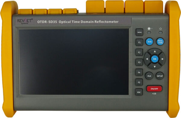
OTDR Basic concepts
OTDR is, again, an acronym. Optical Time Domain Reflectometer. In other words, it is a reflectometer that, in addition to reflecting the reflection and dispersion values, relates them to the time that elapses between the emission of the signal and the reception of the response.
The operation of an OTDR is based on analysing two physical principles that occur in the propagation of light in media with discontinuities. The first is Rayleigh scattering, which locates the event, and Fresnel reflection, which gives us the magnitude associated with that event.
Thus, an OTDR can tell us where a connector, or a merger, or a pinch is located and, at the same time, give us a very precise value of the attenuation that appears because of that event. This is one of the most reliable fibre optic measurement equipment on the market.
Working with an OTDR requires some important concepts to be taken into account.
- The dead zone. In the initial stretch of the measurement, the accuracy of the OTDR is null, so between the OTDR and the installation being tested, a cable of known length in perfect conditions must be intercalated, which we call “launch coil”. There are commercially available launch coils, which are supplied with OTDRs.
- In SM measurements, 1000-metre coils are used, while in MM, a 25 or 30-metre coil is sufficient, as the dead zone is much shorter. The OTDRs themselves have a zeroing system, so that the measurements ignore the launch coil when requested.
- The blind zone. When two events are close together, it is possible that the first event masks the second event and the OTDR identifies them as a single event, located where the first event is and of a magnitude that is the sum of the two. To avoid this as much as possible, the duration of the measurement pulse should be adjusted to the length of the cable under test. In general, the closer the OTDR setup parameters are to the real ones, the more accurate the measurements will be. However, the blind zone is unavoidable, but it can be shortened by adjusting the parameters to only about 3 or 4 metres.
OTDRs normally have a manual and an automatic measurement mode. It is preferable to operate in automatic mode until you have sufficient experience. There are also two measurement modes: real time and average. The average mode performs several measurements over a preset time and presents the average result. Real time mode presents instantaneous results, as captured by the OTDR.
These fibre optic measurement devices have VFL, OPM and OLS, although their capabilities are often limited. The truth is that an OTDR provides more complete and valuable information than a power meter or VFL, but it is good to know that they are also available.
OTDR Interpretation of results
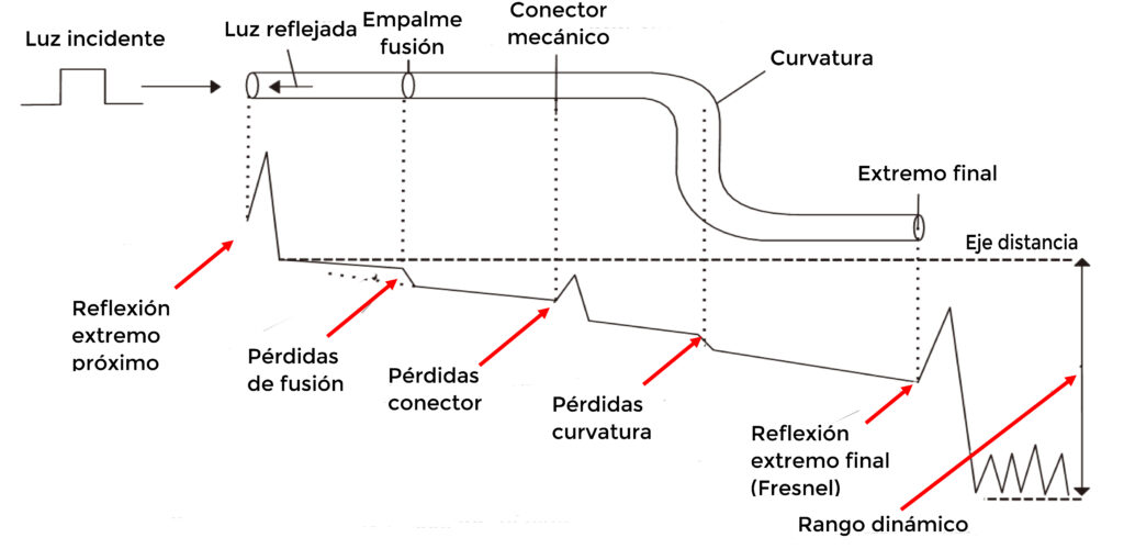
This image summarises the information that we will be able to receive from an OTDR connected to our installation. In the graphs, we will identify the events according to whether they are reflective (start, end, connectors) or only appear as a punctual attenuation. In this case, we are dealing with a merger, excessive bending, pinching, etc.
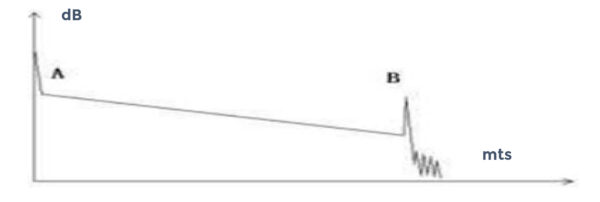
This is the normal graph, which shows no events other than the input connector, the output connector and a small attenuation, due to the power drop in the cable run. The distance between the points A and B will also give the attenuation per km of cable.

In this graph we find a reflective event. That is, there is a connector at this position. The high reflection peak indicates that the connector keeps the two surfaces in perfect condition, and, in addition, the attenuation is very small.
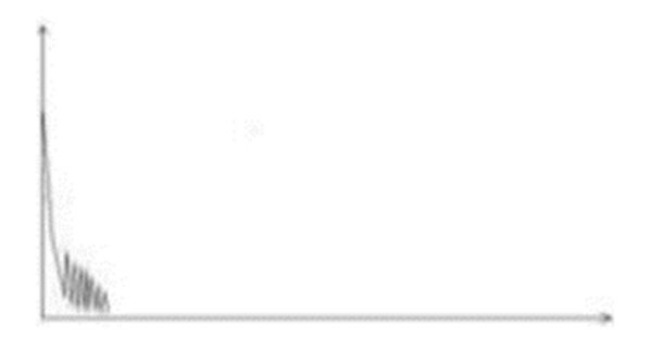
This would be the graph where it indicates a breaking point. The light does not pass from that point.

This is the graph including a non-reflective event, a melt, for example. If we do not have it identified, it is a good idea to repeat the measurement starting at the other end of the cable.
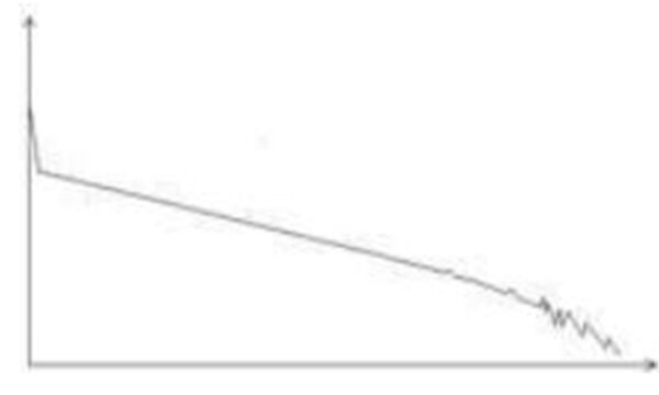
This last graph indicates that we are not using an OTDR suitable for the measurement we want to make. Technically speaking, an OTDR is capable of measuring a cumulative attenuation of, for example, 35 dB for a wavelength of 1550 nm. The observable distance limit is about 125 km. If you try to measure a 200 km cable with such an OTDR, you get such a cure.
OTDRs have a certain dynamic range, the maximum distance they can analyse at a given lambda. They should be chosen to meet your needs. Obviously, an OTDR with a wider dynamic range is a more accurate and therefore more expensive machine.
Similarly, some of these fibre optic measurement devices (OTDRs) are valid for measuring in SM and MM and others only in SM. Think about whether you really need to measure on both types of fibre and at which wavelengths before deciding on one OTDR or the other. In any case, consult a specialist.
The accuracy of the OTDR is, to a large extent, a consequence of a proper parameterisation of the setup. Get a manual that explains it clearly. The manual should be the one for your own OTDR, as each manufacturer uses its own method and there may be important differences and nuances.